


 Oct 28, 2025
 View:2147
You pick up a small electronic part. You see bright color bands on it. You wonder what these colors mean. You also wonder if it is a resistor or a color code inductor. Many people get confused by these bands. The bands look very similar on different parts. Knowing how to read these color codes helps you avoid mistakes. It keeps your projects safe. When you understand the system, you work faster. You fix problems with less effort. Clear color coding lets you see each part’s purpose right away. This makes your work accurate and efficient.
Key Takeaways
Knowing color codes is important for electronics. It helps you find parts fast and avoid errors.
Always look at the color bands from the right side. The tolerance band should be on the right for correct reading.
Use bright light and tools like magnifiers or cameras. This helps you see color bands better and make fewer mistakes.
Inductors and resistors do different jobs in circuits. Knowing how they are different helps you pick the right part.
Keep a printed color code chart close by. This chart can help you work faster and stop you from making expensive errors.
Color Codes in Electronics
Why Color Codes Matter
When you work with electronics, you see many colored bands. These colors are not just for looks. They follow a special system called electronic color code. This system helps you know what each part is. Color coding makes your work easier and safer. It helps you avoid mistakes. You can tell if a part is a resistor or an inductor by the bands.
Tip: Always look at the electronic color code before you put in or change a part. This habit saves you time and stops mistakes.
Here are some big reasons why color coding is important in electronics:
Safety: Color coding helps you find hot, neutral, and ground wires. You can avoid electric shock and fire.
Efficiency in Troubleshooting and Repairs: You find problems faster. You do not waste time looking for the right part.
Regulatory Compliance: You follow the law when you use the electronic color code.
Interoperability and Standardization: Color coding lets you work with other people. Everyone uses the same system.
Future Modifications and Upgrades: You can make changes easily. New workers can read the electronic color code and understand old wires.
Where Color Codes Are Used
You see electronic color code systems in many places. Most resistors and inductors use color bands to show their values. Some capacitors and transistors also use color bands to help you know what they are. You see these codes in many fields:
Consumer Electronics
Automotive
Telecommunications
Industrial Automation
Power Generation, especially renewable energy
The history of electronic color code shows why it matters. Look at this table to see how color coding became a rule in electronics:
| Year | Regulation/Edition | Key Developments |
|---|---|---|
| 1916 | Initial introduction | Started using colors for conductors. |
| 1924 | 8th Edition IEE Wiring Regulations | Made color identification a rule. |
| 1934 | 10th Edition IEE Wiring Regulations | Set colors for phase conductors. |
| 1966 | 14th Edition IEE Wiring Regulations | Used red, yellow, and blue for phases. |
| 1969 | Electrical Appliances (Colour Code) Regulations | Set color rules for mains leads: brown for live, blue for neutral, green/yellow for earth. |
You use electronic color code every time you build, fix, or upgrade a circuit. Color coding helps you work faster and safer. You can trust this system to help you in every electronics project.
Resistor Color Code Basics

How Resistor Codes Work
When you look at a resistor, you see color bands painted on its body. These bands tell you the resistance value and tolerance. The resistor color code uses a set of colors to represent numbers and multipliers. You read these colors in a specific order. Manufacturers follow strict standards from the International Electrotechnical Commission (IEC) to make sure every resistor color code is accurate.
Here is a table that shows what each band means:
| Color Band | Represents |
|---|---|
| 1st | First significant digit |
| 2nd | Second significant digit |
| 3rd | Number of zeros (multiplier) |
| 4th | Percent tolerance (Gold = 5%, Silver = 10%) |
You use the first two bands for the digits, the third for the multiplier, and the fourth for tolerance. Some resistors have a fifth band for extra precision.
The colors follow a standard sequence. Each color stands for a number or a multiplier. You can see this in the chart below:
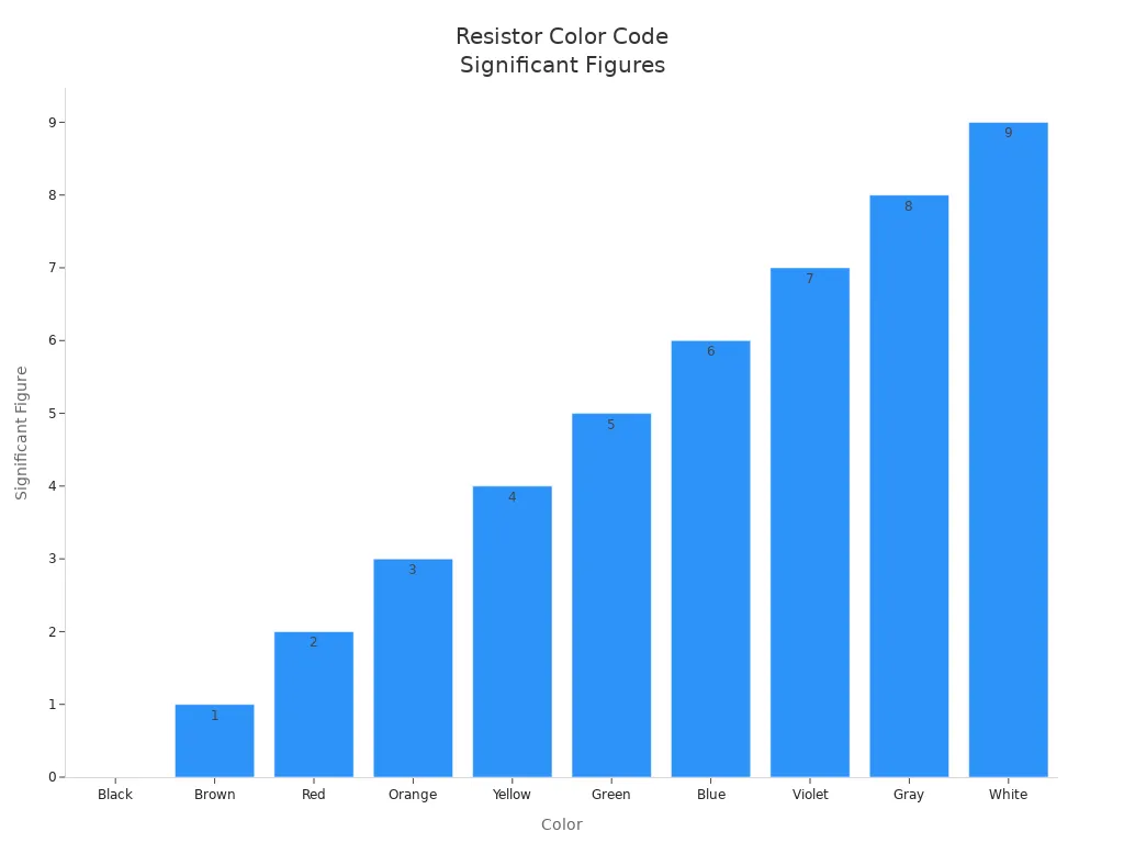
Reading Resistor Bands
You can read a resistor color code by following these steps:
Hold the resistor so the tolerance band (often gold or silver) is on the right.
Look at the first two color bands. Use a chart to find their digit values.
Check the third band for the multiplier.
Calculate the resistance: (First digit × 10 + Second digit) × Multiplier.
Find the tolerance from the fourth band.
Tip: Always double-check the direction before you read the color bands. The tolerance band should be last.
Here is a table to help you match colors to values:
| Color | Digit Value | Multiplier | Tolerance (%) |
|---|---|---|---|
| Black | 0 | ×1 | |
| Brown | 1 | ×10 | ±1 |
| Red | 2 | ×100 | ±2 |
| Orange | 3 | ×1,000 | |
| Yellow | 4 | ×10,000 | |
| Green | 5 | ×100,000 | ±0.5 |
| Blue | 6 | ×1,000,000 | ±0.25 |
| Violet | 7 | ×10,000,000 | ±0.1 |
| Gray | 8 | ×100,000,000 | ±0.05 |
| White | 9 | ×1,000,000,000 | |
| Gold | ×0.1 | ±5 | |
| Silver | ×0.01 | ±10 | |
| None | ±20 |
Common Mistakes
You may make mistakes when reading a resistor color code. Some errors happen often:
| Error Type | Description |
|---|---|
| Misinterpreting Colors | Colors like red and orange or green and blue can look similar in poor lighting. |
| Reading in the Wrong Direction | Starting from the wrong end leads to incorrect values; the tolerance band should be on the far right. |
| Ignoring Temperature Coefficients | Some resistors have an extra band for temperature coefficient, important for precision work. |
If you misread the color bands, you may use the wrong resistor. This can cause your circuit to fail or even damage other parts. You should always check your work and use good lighting.
Note: Careful reading of each resistor color code helps you avoid costly mistakes and keeps your electronics safe.
Color Code Inductor Guide
How Inductor Codes Differ
The color code inductor system looks a lot like the resistor color code. Both use colored bands to show important values. But the color code inductor method is not as strict as the resistor system. This means different companies may use the bands in different ways. Inductors use color bands to show inductance, tolerance, and sometimes temperature coefficient. Resistors use their bands for resistance and tolerance only.
Here is a table that compares the two systems:
| Features | Inductor Color Codes | Resistor Color Codes |
|---|---|---|
| Main Features | Indicate inductance values, tolerance, and temperature coefficients | Indicate resistance values and tolerances |
| Typical Colors | Darkened tones (dark green, black, brown) | Vivid color tones (red, yellow, blue) |
| Number of Rings | 4-6 Rings (including temperature coefficient) | 4-5 rings (some precision resistors have 6) |
| Applications | Energy storage and filtering | Current limiting and voltage dividing |
Most of the time, color code inductor bands follow IEC standards. Some military-grade inductors use special tolerance colors. Brown means ±1%, green means ±0.5%, and purple means ±0.1%. Most regular inductors use gold for 5% and silver for 10% tolerance.
| Standard Type | Description |
|---|---|
| IEC Standards | The color bands on inductors follow the standards set by the International Electrotechnical Commission (IEC). |
| Military Specifications | Military-grade inductors have specific tolerance standards such as ±1% (brown), ±0.5% (green), and ±0.1% (purple), differing from standard inductors which typically have tolerances of 5% (gold) and 10% (silver). |
Reading Inductor Bands
Reading a color code inductor is a lot like reading resistors. The bands tell you the inductance value. This is measured in microhenries (µH), not resistance. Most inductors have four or five bands.
For four-band inductors:
The first two bands show the important digits.
The third band is the multiplier (power of 10).
The fourth band shows the tolerance.
For example, yellow (4), violet (7), red (×100), and gold (5%) means 47 × 100 = 4700 µH with 5% tolerance.
routeros
For five-band inductors:
The first three bands show the important digits.
The fourth band is the multiplier.
The fifth band shows the tolerance.
For example, red (2), violet (7), black (0), brown (×10), and gold (5%) means 270 × 10 = 2700 µH with 5% tolerance.
Some very small inductors use dots instead of bands. These dot-type inductors use raised or sunken dots to show the value, tolerance, and sometimes size.
Here is a table showing the most common band patterns:
| Inductor Type | Number of Bands | Significant Digits | Multiplier | Tolerance |
|---|---|---|---|---|
| Four-ring | 4 | 2 | 1 | 1 |
| Five-ring | 5 | 3 | 1 | 1 |
Tip: Always remember that the color code inductor bands give you the inductance in microhenries. Do not confuse this with resistance values.
Visual Clues for Inductors
You can spot a color code inductor by how it looks and feels. Most inductors have a body color that stands out from resistors. You will often see sea foam green, pea green, or cyan. The bands use darker colors like dark green, black, or brown. This makes them different from the bright colors you see on resistors.
Here is a table to help you compare:
| Characteristic | Inductor Characteristics | Resistor Characteristics |
|---|---|---|
| Typical Colors | Darkened tones (dark green, black, brown) | Vivid color tones (red, yellow, blue) |
| Component Shape | Cylindrical, no pin color difference at ends | Cylindrical shape, different color caps |
| Material Touch | Rough surface (enameled wire or core) | Smooth (ceramic or carbon film) |
You can also feel the difference. Inductors often have a rougher surface because of the enameled wire or core inside. Resistors feel smooth and sometimes have colored caps at the ends.
Note: If you see a part with a sea foam green or cyan body and dark color bands, you are probably looking at a color code inductor. Always check the bands to confirm the value.
Now you know how to tell a color code inductor from a resistor. You can read the bands to find the inductance. You can also use the color and feel of the part to help you identify it quickly.
Inductor vs Resistor: Key Differences
Function in Circuits
Inductors and resistors do different things in a circuit. Resistors slow down the flow of current. Inductors hold energy and change how current moves. Here are some main ways they are different:
Resistors lower the amount of current.
Inductors keep energy and control current.
Inductors help make current smoother.
Resistors keep other parts safe by stopping too much current.
Inductors can hold energy for a long time and make an electric field.
Resistors turn extra energy into heat.
You use a resistor to lower current or split voltage. You use an inductor to store energy or clean up signals. The part you pick depends on what your circuit needs.
Color Code Comparison
Inductors and resistors both have color bands, but they are not the same. The table below shows how their color codes are different:
| Features | Inductors | Resistors |
|---|---|---|
| Main Features | Energy storage, filtering, impedance matching | Current limiting, voltage dividing |
| Typical Colors | Darkened tones (dark green, black, brown) | Vivid color tones (red, yellow, blue) |
| Number of Rings | 4-6 Rings (with temperature coefficient/military coding) | 4-5 rings (some 6 ring precision resistors) |
| Common Labeling | Unit: μH | Unit: Ω (e.g., "102" = 1kΩ) |
Inductors usually have darker colors and sometimes more rings. Inductor color codes show values in microhenries (μH). Resistor color codes show values in ohms (Ω). Some small resistors do not have bands because there is no room. Bigger resistors and inductors show their color codes clearly.
Why the Differences Matter
It is important to know how inductors and resistors are different. Each part changes your circuit in its own way. If you mix them up, your project might not work. Here is why these differences are important:
You make fewer mistakes by reading the right color code.
You keep your circuit safe by using the right part.
You save time by telling parts apart quickly.
You fix things faster because you know what each part does.
You keep your projects working well and safely.
When you know the differences, you feel more sure about your work. You read color codes faster and pick the right part every time. This helps you build better circuits and fix problems quickly.
Using Color Codes in Practice
Real-World Tips
You can make electronics easier by using smart habits. Always look at the color bands before you put a part on your board. Good lighting helps you see colors better. Use sunlight or a bright lamp. A magnifying glass helps you see tiny or faded bands. You can use a digital camera to zoom in and check colors with a chart. Start reading bands from the end near the edge, not from the gold or silver band. This habit helps you make fewer mistakes.
Tip: Keep a printed color code chart at your desk. You can match colors and numbers quickly.
Troubleshooting
Sometimes you might read a color code wrong. This can cause problems in your circuit. You can fix these mistakes by following easy steps. The table below shows common errors and how to solve them:
| Common Mistakes | Solutions |
|---|---|
| Misjudging color ring colors | Use sunlight or a magnifying glass. A camera helps you compare colors. |
| Reading direction errors | Start from the end with the band near the edge. |
| Confusing multiplier units | Remember the base unit is μH for inductors. Change to nH if you need to. |
| Ignoring tolerance and extra bands | Count the rings. Look for temperature or reliability bands if there are more than four. |
You can also do these things to avoid mistakes:
Use good lighting to see colors.
Use a magnifying glass for small bands.
Always start reading from the right end.
Note: Careful reading and checking help you avoid expensive mistakes.
Helpful Tools
You can use many tools to make reading color codes easier. A magnifying glass helps you see tiny bands. Digital cameras or phones let you zoom in and check colors. Free apps and online calculators help you find color band values fast. You can also use printed charts or stickers for quick help.
| Tool Type | How It Helps |
|---|---|
| Magnifying glass | Makes small or faded bands bigger |
| Digital camera | Zooms in for better color matching |
| Color code app | Finds band values and shows numbers |
| Printed chart | Quick help for color meanings |
These tools help you work faster and make fewer mistakes.
You can now tell how resistor and inductor color codes are alike and different. Look at this table for a quick summary:
| Feature | Inductor Color Code | Resistor Color Code |
|---|---|---|
| Main Use | Energy storage, filtering | Current limiting, voltage dividing |
| Typical Colors | Dark green, black, brown | Red, yellow, blue |
| Labeling | μH | Ω |
Try reading color bands on real parts to get better. You can use fun activities like "Resistor Color Code Practice" to learn more. Always use bright light and a color chart when you work. Learning these basics helps you stay safe and do your electronics projects well.
FAQ
How do you tell a resistor from an inductor by looking at it?
You can spot resistors by their bright colors and smooth bodies. Inductors often have darker colors like green or black and feel rough. Inductors may look bulkier. Always check the color bands and body color for clues.
What happens if you read the color code backward?
If you read the bands backward, you get the wrong value. This mistake can cause your circuit to fail. Always start from the end with the band closest to the edge, not the gold or silver band.
Can you use a resistor color code chart for inductors?
You can use the same color-to-number chart for both. The main difference is the unit. Inductors use microhenries (μH), while resistors use ohms (Ω). Always check which component you have before reading the value.
What should you do if the color bands are faded or hard to see?
Tip: Use a magnifying glass or a phone camera to zoom in. Good lighting helps you see faded colors. If you still cannot read the bands, use a multimeter to measure the value directly.


