


What is high frequency transformer vs normal transformer?
 Jun 12, 2025|
 View:1148
Transformers are essential components in electrical and electronic systems, serving the fundamental purpose of transferring electrical energy between circuits through electromagnetic induction. While traditional transformers have been in use for over a century, high frequency transformers represent a more specialized development that has become increasingly important in modern power electronics. This article provides a detailed comparison between these two types of transformers, examining their design principles, operational characteristics, applications, advantages, and limitations.
Fundamental Operating Principles
Normal (Low Frequency) Transformers
Traditional transformers, often referred to as "normal" or "low frequency" transformers, typically operate at power frequencies of 50Hz or 60Hz. These transformers follow the basic transformer equation:
= 4.44 × f × N × B × A
Where:
V is the voltage
f is the frequency
N is the number of turns
B is the magnetic flux density
A is the cross-sectional area of the core
At these low frequencies, the transformer design emphasizes large magnetic cores (usually made of silicon steel laminations) to handle the substantial magnetic flux requirements while minimizing eddy current losses.
High Frequency Transformers
High frequency transformers operate at significantly higher frequencies, typically ranging from several kHz to several MHz. The same fundamental transformer equation applies, but the increased frequency allows for dramatic changes in design approach. Higher frequency operation enables:
Reduced size and weight due to smaller core requirements
Increased power density
Faster transient response
Different core material requirements (ferrites instead of silicon steel)
Design Differences
Core Materials
Normal Transformers:
Use laminated silicon steel (electrical steel) cores
Laminations are typically 0.3-0.5mm thick to reduce eddy currents
High saturation flux density (around 1.5-2 Tesla)
Relatively high core losses at high frequencies
High Frequency Transformers:
Employ ferrite materials (Mn-Zn or Ni-Zn) or powdered iron cores
No need for laminations as ferrites are naturally resistive
Lower saturation flux density (0.3-0.5 Tesla)
Excellent high frequency performance with minimal eddy current losses
Winding Techniques
Normal Transformers:
Use relatively thick copper conductors
Often employ layered or helical winding techniques
May use multiple parallel strands to reduce skin effect (though less critical at low frequencies)
Larger insulation requirements due to higher voltages
High Frequency Transformers:
Frequently use Litz wire (multiple individually insulated strands) to combat skin and proximity effects
Employ sectional or interleaved winding techniques to reduce leakage inductance and parasitic capacitance
Often have fewer turns due to the high frequency operation
May use planar winding techniques in PCB-based designs
Size and Weight Considerations
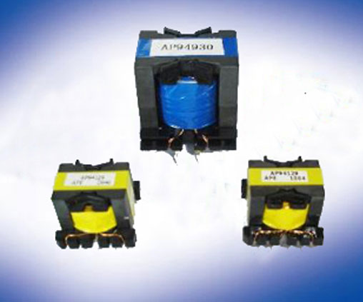
The most noticeable difference between the two transformer types is their physical size relative to their power handling capacity. High frequency transformers can be 5-10 times smaller than their low frequency counterparts for the same power rating. This size reduction comes from two factors:
The increased frequency allows for fewer turns to achieve the same voltage transformation
The reduced flux requirement permits smaller core cross-sections
Performance Characteristics
Efficiency Considerations
Normal Transformers:
Typically achieve 95-99% efficiency at rated load
Losses dominated by:
Copper losses (I²R losses in windings)
Core hysteresis losses
Eddy current losses in the core
Efficiency optimized for a narrow frequency range (50/60Hz)
High Frequency Transformers:
Efficiency generally lower, typically 85-95%
Loss mechanisms include:
Skin and proximity effects in windings
Core losses that increase with frequency
Dielectric losses in insulation
Efficiency varies significantly with frequency and requires careful design optimization
Thermal Management
Normal Transformers:
Larger surface area facilitates natural cooling
Often use mineral oil or other coolants in power applications
Thermal time constants are relatively long
High Frequency Transformers:
Higher power density creates challenging thermal management requirements
Often require forced air cooling or heat sinks
May use thermal vias or other techniques in planar designs
Thermal time constants are shorter due to smaller mass
Parasitic Elements
Normal Transformers:
Leakage inductance is relatively high but less critical at low frequencies
Winding capacitance is generally not a significant concern
Parasitic effects often modeled as lumped elements
High Frequency Transformers:
Leakage inductance and winding capacitance become critical design parameters
Parasitic elements can significantly affect performance and mu
st be minimized
Often require complex distributed parameter models
May need resonant techniques or snubber circuits to manage parasitics
Applications
Normal Transformer Applications
Power distribution networks (step-up and step-down transformers)
Utility power supplies for industrial and residential use
Audio frequency applications
Line frequency power supplies for traditional electronics
Isolation transformers for safety
High Frequency Transformer Applications
Switch-mode power supplies (AC-DC and DC-DC converters)
RF circuits and communication systems
Induction heating systems
High frequency inverters (for renewable energy systems)
Aerospace and military power systems where size/weight are critical
Electronic ballasts for lighting
Wireless power transfer systems
Advantages and Disadvantages
Normal Transformers
Advantages:
Proven, reliable technology with well-understood characteristics
High efficiency at design frequency
Can handle very high power levels (up to hundreds of MVA)
Simple construction with readily available materials
Long operational life with minimal maintenance
Disadvantages:
Large and heavy for their power rating
Limited to narrow frequency range
Poor performance at frequencies other than design frequency
Difficult to adapt to modern power electronics applications
High Frequency Transformers
Advantages:
Compact size and light weight
Can be integrated into PCB designs (planar transformers)
Enables high power density systems
Faster transient response
More suitable for modern power conversion topologies
Disadvantages:
More complex design process
Higher losses per unit power
Core materials more sensitive to temperature variations
More susceptible to parasitic effects
Limited maximum power handling compared to large power transformers
Future Trends
The evolution of transformer technology continues to push toward higher frequencies and greater power densities. Emerging developments include:
Advanced Core Materials: New nanocrystalline and amorphous materials offering better high frequency performance with lower losses.
3D Printing: Additive manufacturing techniques enabling complex transformer geometries that were previously impossible to fabricate.
Wide Bandgap Semiconductors: Devices using SiC and GaN technologies enabling even higher frequency operation of power converters, driving transformer designs to higher frequencies.
Integrated Magnetics: Combining multiple magnetic functions (transformers, inductors) into single components to reduce size and improve performance.
Smart Transformers: Incorporating monitoring and control electronics directly into transformer designs for improved reliability and performance.
The choice between high frequency and normal transformers depends fundamentally on the application requirements. Normal transformers remain the undisputed solution for utility-scale power distribution and low frequency applications where size and weight are secondary concerns. High frequency transformers, by contrast, enable the compact, efficient power conversion needed in modern electronics, renewable energy systems, and specialized applications where space and weight are at a premium.
As power electronics continue to evolve toward higher frequencies and greater efficiencies, the importance of high frequency transformer technology will only grow. However, both transformer types will continue to coexist, each serving distinct but vital roles in our electrified world. The ongoing development of new materials and manufacturing techniques promises to further enhance the capabilities of both transformer types, ensuring their relevance in future power systems.


